In this project, you are going to configure a simulated Internet in the virtual world, so that you can send messages from any treehouse to any other treehouse using a protocol that models the Internet Protocol. The network consists of nodes, some of them terminal (modeling home computers), others intermediary (modeling ISP routers and even backbones). Here is how they look like:
At the end of the project, your terminal in your treehouse should be able to send messages to any other terminal in any treehouse of the virtual world. The Litmus test is whether messages reach the destinations or not.
The actual work you need to to is pretty minimal, but in order to do it correctly and effectively, you need to:
This project is as much an exercise in network configuration as it is an exercise in student coordination, because the configuration of the network is not just done by one student but by all of you! You will need to organize in groups that reflect the hierarchical structure of the simulated Internet. By doing so, you will also learn about the social and commercial aspects of the Internet.
Make sure to watch all the videos in the Network lecture in Tuesday, and don't miss the live lecture on Thursday (or watch the video afterwards).
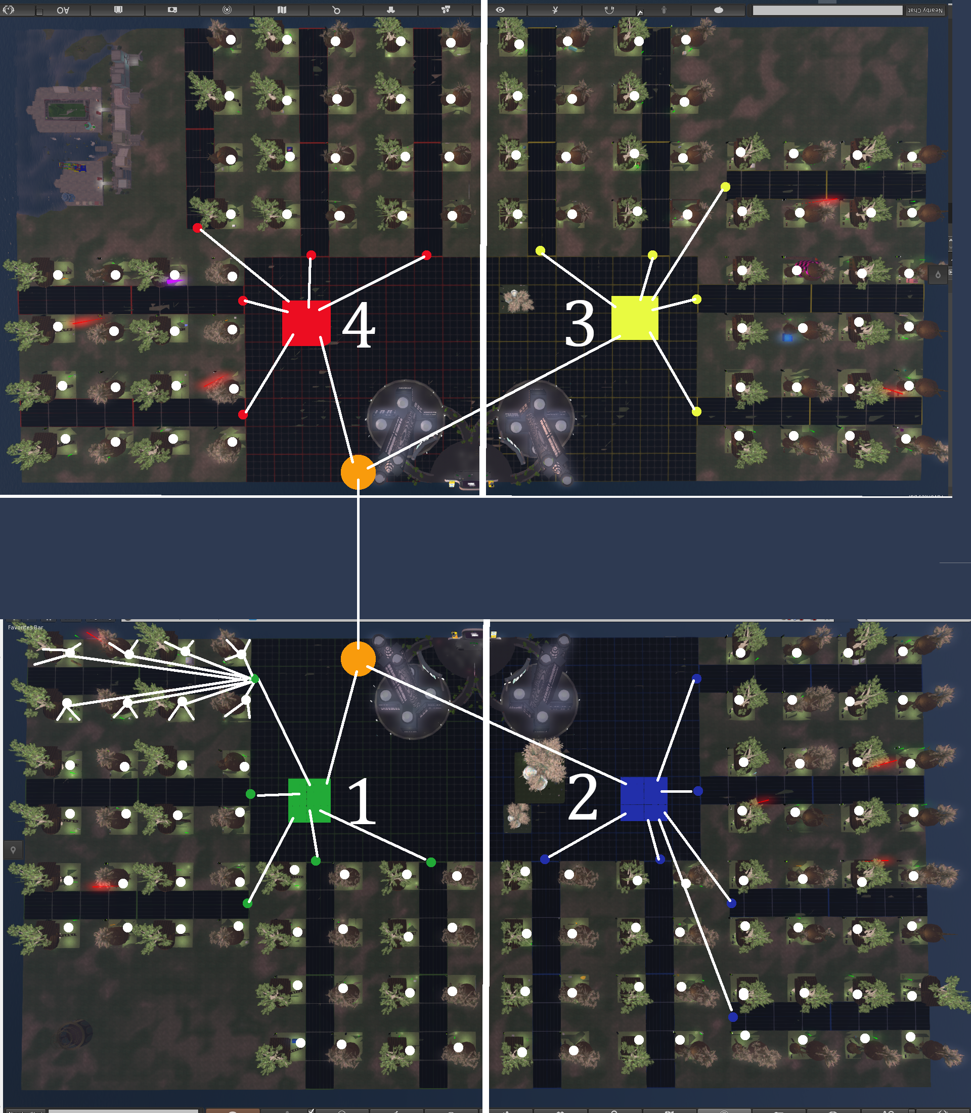
If you pull up the map (Cntrl-m), you will see something like this:
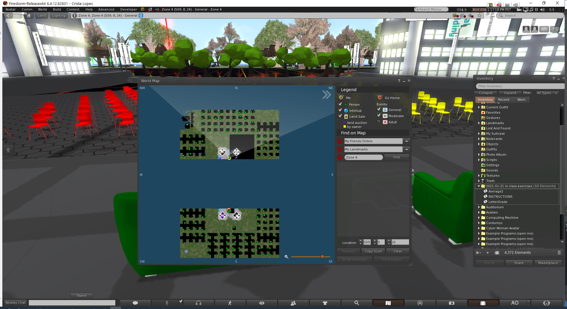
The virtual world is divided into two halves: North side and South side. In between them, there is the ocean. You cannot cross from one half to the other by walking, but you can teleport. In the real world these correspond to continents separated by oceans, such as America and Asia.
Furthermore, each half is divided into 2 zones. On the South side, there is Zone 1 (green) and Zone 2 (blue); on the North side there is Zone 3 (yellow) and Zone 4 (red). In the real world, these might correspond to countries.

Technically, each zone is served by a separate game server, so to balance the load, but you don't need to worry about that. The only thing you need to know is that each of these zones is a square of 512x512m2. Also, the North side and the South side are separated by a distance of 512m.
Zones, like countries, are relatively independent of each other. Specifically, the coordinates in each zone are local coordinates whose (0,0) point is the southwestern-most corner of each square. In each zone, the X axis (horizontal) increases left to right, and the Y axis (vertical) increases bottom to top. So, for example, the South side auditorium is, roughly between (312, 400) and (512, 512) in Zone 1 and between (0, 400) and (200, 512) in Zone 2. In each zone, you can refer to points outside of it by using coordinates that are greater than 512 (to the right / to the top) or negative (to the left / to the bottom). So, for example, with respect to Zone 3, the South side auditorium in Zone 1 is, roughly between (-200, -624) and (0, -512).
From the picture above, we can see how the regions are organized. In each region there are several streets, each with two rows of treehouses (an exception is Zone 4, the street near the Boardwalk mall, which has only 4 treehouses). The streets are numbered, rather than named. Here's one example of a street number -- you will find these signs in every street:

Your first task is to identify the Zone and Street of your treehouse! This is very important for this project, as that will determine which groups you belong to, and which network nodes you are responsible for. So go ahead, and identify your zone/street.
The virtual world does not specify numbers for treehouses, but each treehouse should be associated with a number between 1 and 10 that is unique within each street. You will need to coordinate with your street neighbors, so that each of you gets a unique number; there should be no duplicates within a street.
You are going to simulate the Internet. The Internet is a hierarchical network -- a network of networks. So is this simulated network! The following picture illustrates the hardware and connections that you will need to put in place:
Let me explain this picture in parts:
Independent of whether a router is a home-level, street-level, region-level, or continent-level, all routers do exactly the same thing: they route messages upstream and downstream according to their internal routing tables. For that reason, your package contains only one type of router.
Just like IP addresses, the network addresses here are hierarchical. Our addresses consist of 4 parts: zone, street, house, and terminal. Here is an example of a network address in our simulated Internet:
3.4.1.2
This address identifies terminal 2 in house 1 in street 4 of zone 3. The format, in general, is zone.street.house.terminal, but some parts are optional:
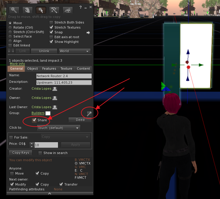
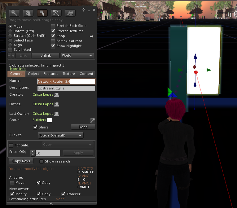
Every node in the network must be identified by an address, and that address needs to be entered in the node objects. In order to do that, right-click on the node object (terminal or router), chose "Edit", and then the tab "General." The name should be "Network Router:" or "Network Terminal:" followed by an address. Here is an example:
The first time you enter the Name of a node, and every time you change it, you must reset it by right-clicking on the object, then choosing "More", then "More" again, then "Scripts", then "Reset Scripts".
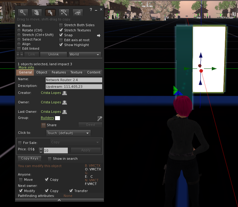
In order to "connect" nodes, we are going to use their spatial coordinates, so that nodes can "physically" send messages to other nodes. You can find out the coordinates of an object (for which you have permission to inspect) by right-clicking on the object, choosing "Edit", and then going to the tab "Object." Here is an example:

You only need to use the integer part of the coordinates, not the decimal part. So, round up or down for integer coordinates x, y, z.
Connecting any two nodes is done by configuring their upstream and downstream routes. In this network, nodes can only have one upstream route, but many downstream ones. For example, according to the topology picture above, street-level routers connect to only one region-level router (upstream) but to many terminals (downstream).
Upstream configuration: because there is only one, the upstream configuration is done using the object's "Description" field. Right-click on the object, chose "Edit" and then chose the "General" tab. Then fill out the Description field with the following:
Upstream: x, y, z
where x, y, and z are the coordinates of the upstream router to which the node you are configuring should be connected. Please keep the word "Upstream" followed by a ":' before entering the comma-separated coordinates. Here is an example:
What this means is that this node (in this case, a streel-level router) will send incoming upstream messages to location 111, 405, 23, where, supposedly, there is a region-level router.
When you enter the upstream information for the first time, and every time you change it, you need to reset the node: right-click the object, chose "More", then "More" again, then "Scripts", then "Reset Scripts."
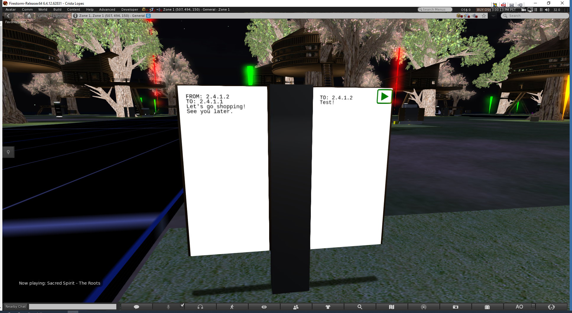
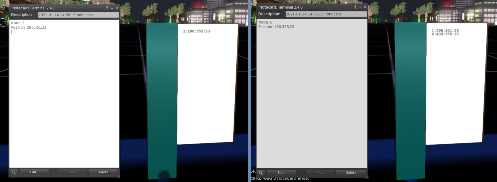
Downstream configuration: because there are many downstream nodes, downstream configuration is done by dragging notecards onto the panel of the routers. The information in the notecard should include the downstream node and its coordinates, for example:
Node: 6
Position: 430, 355, 23
This information relates to downstream nodes, so it only needs to identify them by a single number, not three. In the example above, node 6 identifies node 6 downstream from the router that we are configuring.
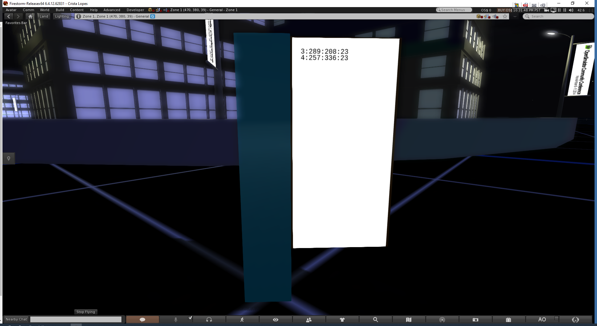
Each notecard adds exactly one entry; it does not replace what is already there! The following picture shows what happens after entering the first notecard, and then the second notecard:
Also, once entered, the routing information of a downstream node cannot be changed! If, for any reason, you find yourself needing to replace the coordinates of a node in a routing table of a router, you need to reset the router, which will make it erase all the information. So, before you do that. make sure to store elsewhere the information that is not supposed to change, so you can load it again. In any case, here is how you can reset routers: right-click the object, chose "More", then "More" again, then "Scripts", then "Reset Scripts."
In order to be able to configure the entire set of 150+ nodes, you need to coordinate with your fellow students. Here are some of the things that you need to coordinate:
In order to facilitate this coordination, there are several inworld groups which you can join and use to chat (while logged in). Specifically, there are street-level groups, as well as region-level and continent-level groups. To join, click the search button on the bottom of the screen, go to groups, and type:
You can also organize inworld meetings in someone's treehouse using voice.
Optionally, you can organize outside of the world, in the student's Discord server. Or in any other way that works for you and your groups!
Permissions
Objects that you place inworld belong to you, and cannot be edited by anyone else. This is a problem for street, zone, and backbone routers, because many students will, at least, need to see their inworld coordinates. Luckily, objects can be shared with groups. In order to share objects inworld, right-click and "Edit", then go to the "General" tab. Locate the "settings" button, click on it, and chose the right group to share the object with. Then check the checkbox "Share."