At the 1st ACM-SIAM Symp. on Discrete Algorithms, in 1990, Walter Schnyder presented a very nice algorithm for placing the vertices of a planar graph on a grid, so that the straight line segments between the vertices form a planar drawing of the graph.
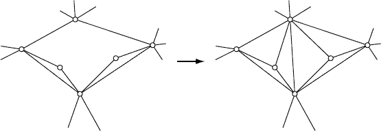
The input to Schnyder's algorithm is assumed to be a planar graph, without any self-loops or multiple adjacencies, with the topology of a planar layout already specified in terms of a clockwise ordering of the edges at each vertex, as results from Hopcroft-Tarjan or other linear-time planar embedding algorithms. In addition, each face of the layout, including the outer face, is assumed to be a triangle. If necessary, one can add edges to the graph to subdivide the faces into triangles, using the following fact (which we will also need later):
Lemma 1: Let G be an outerplanar graph (planar graph in which some face f contains all the vertices). Then there is a vertex in G whose only neighbors are the two adjacent vertices in f.
Proof: As we saw when discussing properties of planar graphs, the weak dual of G (the graph formed from the planar dual by removing the dual of f) is a tree. This tree has a leaf, corresponding in G to a face l that shares all but one of its edges with f. Since l has at least three vertices, the path of edges between l and f contains a vertex, which has as its neighbors only the adjacent vertices on the path. This vertex satisfies the conditions of the lemma.
So if any face is not a triangle, we can use the lemma (on the graph of edges connecting the vertices of that face) to find a vertex that can be connected to all other vertices of the face, subdividing the face into triangles, without adding any multiple adjacencies, as shown below. With some care, all faces can be triangulated in this way in linear time.
One of the faces of the graph will be designated as external, and the rest as internal. An edge or vertex is internal if it does not belong to the external face. Schnyder's method depends on two closely related concepts in a triangulated planar graph: a normal labelling and a realization. A normal labelling is an assignment of the numbers 1-2-3 to the corners of each interior triangle, such that each triangle has all three labels in clockwise order, and so that the labels around each internal vertex form contiguous blocks of 1's, 2's, and 3's in clockwise order. A realization is an assignment of a direction to each internal edge, and a number 1-2-3 to each internal edge, so that each internal vertex has exactly one outgoing edge with each of the three numbers, these edges appear in clockwise order, and between any two outgoing edges labeled i and j the incoming edges all have label 6-i-j. Below we see a normal labelling and a realization of the same graph.
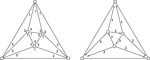
Any internal edge in a normal labelling must have all three labels at the adjacent triangle corners, two different label at one end and the same label twice at the other end. We can form a realizer by orienting each edge toward the end with the doubled label and giving it that label. Conversely if we have a realizer we can form a normal labelling by assigning the label 6-i-j to all corners between the outgoing edges labeled i and j. If you check the illustration above you will see that the normal labelling and realizer are related to each other in this way. So the two concepts are equivalent and easily converted to each other.
Lemma 2: In any realizer, all edges at an external vertex are oriented towards that vertex, and have the same label.
Proof: By Euler's formula, The number of internal vertices is n-3, and the number of internal edges is 3n-9. Each internal vertex has three outgoing edges, so the number of edges outgoing from internal vertices is also 3n-9, and there are no edges left over to be outgoing from external vertices. Since all edges in the realizer are oriented towards an external vertex, all corners at that vertex in the corresponding normal labelling must have the same label, and so all edges in the realizer must have the same label as well.
In any realizer, the path of edges around one of the outer corners of the drawing starts and ends with an edge pointing outward, so there must be a vertex in the middle of the path where both edges point away from that vertex. Contracting that vertex into the outer corner produces a realizer of a graph with one fewer vertex.
Lemma 3: In any realizer, the edges with label i form a spanning tree of the internal vertices rooted at the external vertex with label i.
Proof: by induction on the size of the graph, using the contraction step described above to reduce to a smaller graph.
Conversely, any planar triangulation has a vertex along this path that can be contracted into the outer corner without creating multiple adjacencies (by Lemma 1, applied to the vertices of the path), and one can construct a realizer of the original graph by uncontracting a realizer of the contracted graph. This allows us to develop a linear time algorithm for normal labelling of a planar triangulation, expressed below in pseudo-Python syntax:
def normalLabel(G):

    # set up data structures
    stack = []
    neighborCounts = {}
    contractible = []
    for v in the path of edges around external vertex 1:
        neighborCount[v] = number of edges from v to other vertices in the path
        if neighborCount[v] == 2:
            contractible.push(v)

    # repeatedly contract
    while graph has internal vertices left:
        v = contractible.pop()
        stack.push(v)
        contract v into the external vertex
        for w in the vertices added to v by the contraction:
            adjust neighborCounts[neighbors of w]
            move vertices into or out of contractible if count becomes ==2 or !=2

    # build graph back up by reversing contractions
    while len(stack) > 0:
        uncontract(stack.pop())
        label the two new uncontracted triangles
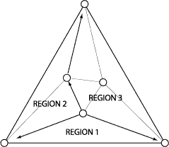
Finally, we are ready to define the grid embedding of the graph. Since the realizer of the graph has a spanning tree for each label, there is a path of label-i edges from each vertex v to external vertex i. These three paths divide the graph into three regions:
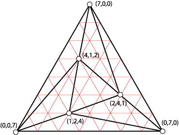
We use the numbers of triangle in each region as three-dimensional coordinates of v. Any set of coordinates (x,y,z) has x+y+z=2n-5, so these coordinates all lie on a plane. Any triangle in the graph is oriented correctly, since its corner labeled i has the highest i'th coordinate of the three vertices in the triangle. Since all triangles are oriented correctly, the layout can't fold over itself and must be non-crossing. The layout of the example we've been using is shown below. Although the coordinates are 3-dimensional, we can view them as barycentric coordinates in a two-dimensional triangular grid: position (x,y,z) is x lines above the bottom edge of the triangle, y lines to the right of the left edge, and z lines to the left of the right edge. Alternatively, we can form a layout on a square grid by dropping the third coordinate.
Schnyder goes on to find a slightly compacter layout, by counting vertices in each region (including the path bordering the region on the clockwise side but not on the counterclockwise side). The result is an embedding with positive integer coordinates in the plane x+y+z=n-2, or in two dimensions in an (n-2)x(n-2) grid, in linear time.