Sets
Relations
Correspondences
Ordered Sets
Lattices
Graphs
Powersets
Binary Strings
Logic
AIA
Greek
Glossary
Abstracts
Argument
Inquiry Cycle
Legal Relations
Presentations
Elicitation
Glossaries
Goals
i*
SCR
Tracing
Design Patterns
Javadoc
Java Packages
Java Types
MSCs

Figure 1. An MSC [from ITU1999-msc p.21]
A (basic) message sequence chart or MSC is a diagram that shows communications between system components (also called instances). Each vertical line in an MSC represents a system components, and horizontal arrows represent messages from one component to another.
It is a design-level notation, intended for and best suited for system design involving two or more subsystems; it is not particularly appropriate for system requirements.
There is also the high-level message sequence chart or hMSC, which gives the order in which some MSCs can occur.
Interpreting an MSC
An MSC shows the sequence in which some messages are sent among some components (sometimes called instances). The vertical line for each component/instance is its axis. The messages and components have to be defined elsewhere. Each message m has two instants in time: when it is sent by one component (out(m)) and when it is received by another (in(m)). The sequence is as follows:
- Each message is sent before it is received (out(m) precedes in(m)).
- For each component, messages higher on the vertical line precede messages lower down.
- But there is no other guarantee about the sequence of messages on different vertical lines. For two messages that don't share a component, it doesn't matter which is higher or lower in the diagram. For people who like MSCs, this is their greatest charm and power; for everyone else, it is a confusing annoyance.
- Also an MSC may describe an implementation that is inconsistent, in that the components may not have enough information to enforce the message ordering the MSC defines. Although one might see this as a defect in the notation and its semantics, MSC enthusiasts view this as an opportunity for analysis instead.

Figure 2. Partial order of outs and ins in Figure 1
For example, in Figure 1
- the arrival of m1 in(m1) is followed by the sending of m2 out(m2) (rule 2),
- which is followed by the arrival of m2 in(m2) (rule 1).
- But although m3 is higher in the diagram than m4, we don't know whether or not m3 arrives before m4 is either sent or arrives, because the three instants happen at different components (rule 3). It could be that m3 arrives after m4 (in(m3) > in(m4)), even though m3 is higher in the diagram — higher in the diagram makes no difference except for messages at the same vertical line (component).
- It is also the case that although the MSC demands that out(m3) precede in(m4), in fact there is no way to enforce this (rule 4). Component proc_b can't tell when proc_a sends m3, so it can't make sure that m4 doesn't arrive until later.
Figure 2 gives the partial order of message ins and outs in Figure 1.
Figure 1 also shows:
- the instance head
 and instance end
 symbols,
which mark the beginning and end of a description
(not the creation and destruction of the component described).
The instance's axis runs from the instance head to the instance end.
symbols,
which mark the beginning and end of a description
(not the creation and destruction of the component described).
The instance's axis runs from the instance head to the instance end.
- a message (m1) that originates from outside the frame (the rectangle surrounding the MSC), coming from some other component not described in the MSC. Such a message is called a gate.
Other MSC possibilities
- Messages can be "lost" (indicated by
 ),
meaning that their input is unknown.
),
meaning that their input is unknown.
- Messages can be "found" (indicated by
 ),
meaning that their output is unknown.
),
meaning that their output is unknown.
- An instance (component) may be described with a
named unit of behavior, called a method.
A method is shown as a filled rectangle on the instance's axis.
I believe a method is called by a message.
The result of a method is returned by a reply
(indicated by
 ).
).
- If the calling instance is suspended (waiting, inactive) until the reply arrives, this is denoted by an open rectangle on the calling instance's axis.
- A condition
(indicated by
 blocking one or more instance axes)
must be true for its axis or axes to proceed.
The condition that must be true is named in the lozenge shape.
A guarding condition is identified by the keywords
"condition when"'
such a condition must be true in order for its axes to proceed.
A setting condition,
identified by the keyword "condition",
is guaranteed to be true when its axes pass it.
blocking one or more instance axes)
must be true for its axis or axes to proceed.
The condition that must be true is named in the lozenge shape.
A guarding condition is identified by the keywords
"condition when"'
such a condition must be true in order for its axes to proceed.
A setting condition,
identified by the keyword "condition",
is guaranteed to be true when its axes pass it.
- A timer
(indicated by
 )
is used to show timeouts or delays.
)
is used to show timeouts or delays.
- A coregion ... under construction
- An inline expression ... under construction
- An MSC reference (a call of another MSC) ... under construction
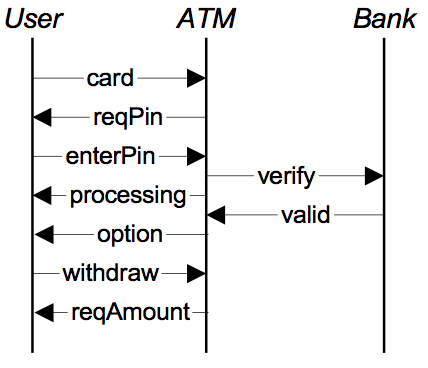
Figure 3. ATM [from Letier+Kramer+2005-mcsb p.387]
Some example MSCs
Figure 3 shows a user going through the beginning of an ATM withdrawal transaction. The diagram assumes that we have definitions of the components and messages, and simply gives the sequence of the messages. "User" is the user, "ATM" is the ATM, and "Bank" is the bank's database system with which the ATM communicates. The user inserts an ATM card, the ATM requests a PIN, the user enters a PIN; the ATM verifies the PIN with the bank's database. The "processing" message stands for the ATM showing a message saying it is processing the PIN. After the bank says the PIN is valid, the ATM presents the transaction choices ("option") and the user selects withdrawal. The ATM then asks for the amount to withdraw.
Although this MSC states that the ATM shows the "processing" message before the bank responds with "valid", in fact the implementation that the MSC describes cannot ensure this because the ATM doesn't control how quickly the bank responds. Granted, this is a fairly insignificant problem but is an example of how an MSC can state a property that the implementation it describes cannot guarantee.
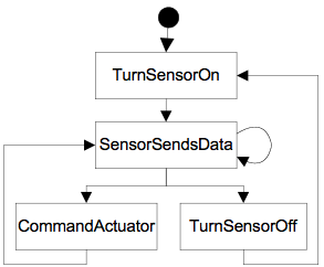
Figure 4. hMSC relating four basic MSCs
hMSCs
A high-level message sequence chart or hMSC gives the sequence in which some basic MSCs can occur. An example is shown in Figure 4.
UML sequence diagrams under construction

Figure 5. Sequence diagram
A UML sequence diagram or SD is similar to an MSC but written with a different notation. Presumably the same semantic issues arise, but possibly not since UML semantics are not well-defined. An example is shown in Figure 5.
The timelines are dotted rather than solid, and the name of the component is inside a box at the head of each timeline. The narrow rectangles apparently show when a component is active (unsure precisely what "active" means). An X on a timeline indicates that the component ceases to exist in some sense (unsure precisely how this is meant also). In the example, the Bank timeline has an X simply as an example (presumably the Bank does continue to exist).
References
- ITU1999-msc
-
Message Sequence Chart (MSC).
ITU-T Recommendation Z.120.
International Telecommunications Union.
Nov. 1999.
- Letier+Kramer+2005-mcsb
-
Emmanuel Letier, Jeff Kramer, Jeff Magee, and Sebastian Uchitel.
Monitoring and control in scenario-based requirements analysis.
In 27th International Conference on Software Engineering (ICSE ’05), pages 382–391,
15–21 May 2005.
Abstractdoi:10.1145/1062455.1062527

