Sets
Relations
Correspondences
Ordered Sets
Lattices
Graphs
Powersets
Binary Strings
Logic
AIA
Greek
Glossary
Abstracts
Argument
Inquiry Cycle
Legal Relations
Presentations
Elicitation
Glossaries
Goals
i*
SCR
Tracing
Design Patterns
Javadoc
Java Packages
Java Types
About SCR
Overview of SCR requirements document
Kinds of items defined in the document
The tables
Mode tables
Initial mode tables
Mode transition tables
Selector tables
Condition tables
Event tables
The sections of the A7-E requirements document
Examples from A7-E requirements document
//STEEREL// selector table (p.259)
Azimuth cursor position condition table (p.256)
//AUTOCAL// event table (p.243)
References
About SCR
The Software Cost Reduction project at the Naval Research Lab re-developed the avionics software for the Navy's A7-E aircraft, using approaches based on software engineering research rather than ordinary practice, and comparing the results to the original development effort using a battery of statistical information. The most successful product of this project was the requirements document structure, which has been used elsewhere and expanded and is currently supported by a sophisticated analysis tool. SCR requirements documents separate concerns by giving most of the information in tables, and make the type of each term in the document evident using special brackets.
SCR-style requirements specifications are most suited to embedded systems, or to any system with a fixed set of inputs and outputs. They are not well suited to a system whose sets of input and output items may vary (such as an elevator system parameterized to serve any number of floors), or whose set of states is not fixed (such as a text editor).
This document presents the SCR requirements specification structure, based on [AFB+92].
Overview of SCR requirements document
An SCR requirements document describes the externally visible behavior of a system, by defining the values of each output of the system. The outputs are defined not in terms of the inputs, but rather as functions of the system's environment. The inputs are also described as functions of the system's environment, but they are not otherwise used. To simplify the description of these functions and to help make the descriptions consistent, special terms are defined and used throughout the descriptions. The description of these functions is further simplified by dividing the system's overall state into modes in which these functions' values may differ; then an output can be specified by separate functions for different modes. The behavior is further subdivided by defining the possible undesired events (UEs) and describing the desired behavior in those cases separately.
The major parts of an SCR requirements document are
- the definitions of the inputs, outputs, terms, and other items;
- the tables that define the system modes and transitions between them; and
- the tables that define the values of items that are mode-dependent.
The division of kinds of information as described above helps separate concerns and reduce the amount of information that a person must keep in mind at any one time. Where possible, formal descriptions (mathematical and logical) are encouraged instead of prose, because such descriptions are more likely to be "precise, concise, consistent, and complete" [AFB+92 p.v]. Tables are used wherever possible in order to present information more clearly and concisely and to make any missing information obvious. A guiding principle of SCR documents is that each piece of information should be stated exactly once, and then be referenced wherever it might otherwise be restated. The resulting requirements document is straightforward to use as a reference, easy to change, and its areas of incompleteness are easy to identify.
Note that this description doesn't take into account the Four-Variable Model [PM95] or other later developments from SCR researchers.
Kinds of items defined in the document
The SCR form divides the requirements specification into several different kinds of item, most with their type identified by special brackets. For example, the name of each input to the system is enclosed in /'s, like /IMSMODE/, and the name of each output in //'s, like //AUTOCAL//. This allows a reader to instantly identify the type to which even an unfamiliar item belongs. The document is organized to make each item definition quick to find.
- /input/
- Inputs to the system.
- //output//
- Outputs from the system. The values of the outputs are given as expressions, usually involving the system inputs.
- $value$
- Special values of inputs and outputs.
- !term!
- A term or expression that is defined in one place and used in several or many places. One frequent use of terms is for complex expressions whose values describe inputs or outputs.
- *mode*
-
The system's behavior may be classified into modes of operation,
and the system's behavior specified differently in the different modes.
Modes are partitioned into mode classes, and
each mode belongs to exactly one mode class.
While the system may be in several modes at once,
it is in only one mode from each class
at any particular time [AFB+92 p. 175].
Table 1. The A7-E expression operators Operator Type Definition < Relational less than ≤ Relational less than or equal to > Relational greater than ≥ Relational greater than or equal to ≠ Relational not equal to = Relational (= is not listed in [AFB+92 p.5] but is used) ABS(x) Numeric absolute value MAX(x,y) Numeric maximum MIN(x,y) Numeric minimum SIGN(x) Numeric signum (-1, 0, +1 when x is negative, zero, or positive) AND Logical conjunction OR Logical disjunction NOT. Logical negation - condition
- Conditions have the value true or false, and may be constructed from /input/s, /output/s, $value$s, literal data values, and the usual panoply of relational operators (the ones in the A7-E document are listed in Table 1). Any operator may be used as long as its meaning is defined in the requirements specification.
- @event
- @T(condition) is the event that occurs whenever condition changes from false to true; @F(condition) is the event that occurs whenever condition changes from true to false.
The tables
The values of all but the simplest /input/s, //output//s, and !term!s vary depending on the system mode. Tables are used to show the values of these items. Tables are also used to describe the transitions between modes. The kinds of SCR tables are described below.
| Kind of table | When used |
|---|---|
| Mode tables | To show what *mode* the system is in at a given time |
| Selector tables | To define an item whose value depends on the current *mode* |
| Condition tables | To define an item whose value depends on the current *mode* and one or more conditions |
| Event tables | To define an item whose changes in value are triggered by an event in some *mode* |
The example tables are the ones given in [AFB+92 ch.0].
Mode tables
Initial mode tables
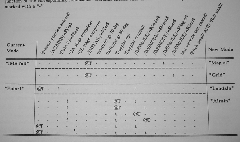
Figure 1. Example mode transition table from [AFB+92]
An initial mode table defines which mode(s) a system begins in as a function of conditions that are true when the system is started.
| Event table x: When Zip is Turned On/Off | |
|---|---|
| MODES | DEFINING CONDITIONS |
| *Mode1* | A |
| *Mode2* | B |
Mode transition tables
A mode transition table describes the events that cause the system to change from one mode to another.
(In [AFB+92] the mode transition tables are laid out with the current and new modes in columns, and the condition values in columns headed by the condition name angled upward at about a 60° angle, as in Figure 1. Because this is difficult to achieve in HTML, the example table below is presented reflected across the diagonal; it is otherwise identical to the table in Figure 1.)
| Current Mode | *IMS fall* | *PolarI* | |||||||
|---|---|---|---|---|---|---|---|---|---|
| !present position entered! | - | - | @T | - | - | - | - | @T | @T |
| /ACAIRB/=$Yes$ | - | - | - | - | - | - | - | - | - |
| /Data23/=$Sea$ | - | - | f | - | - | - | - | - | - |
| !CA stage complete! | - | - | - | f | f | f | f | - | - |
| /IMSFAIL/=$Yes$ | - | - | - | - | - | - | - | - | - |
| !latitude!>70° | - | - | - | - | - | - | - | - | - |
| !latitude!>80° | - | - | - | - | - | - | - | - | - |
| !Doppler up! | - | - | - | @T | @T | t | t | t | t |
| !Doppler coupled! | - | - | - | - | - | - | - | - | - |
| /IMSMODE/=$Gndal$ | - | - | t | t | - | @T | - | t | - |
| /IMSMODE/=$Norm$ | - | - | - | - | t | - | @T | - | t |
| /IMSMODE/=$Iner$ | - | - | - | - | - | - | - | - | - |
| /IMSMODE/=$Mag sl$ | t | - | - | - | - | - | - | - | - |
| /IMSMODE/=$Grid$ | - | t | - | - | - | - | - | - | - |
| !Air velocity test passed! | - | - | - | - | - | - | - | - | - |
| !Pitch small! AND !Roll small! | - | - | - | - | - | - | - | - | - |
| New Mode | *Mag sl* | *Grid* | *Landaln* | *Airaln* | |||||
| Selector table x: Description of ACT and BE | ||
| MODE | //ACT// | //BE// |
| *MODISH* | $Vogue$ | $Cool$ |
| *LASTING* | X | *Warm* |
Selector tables
A selector table gives the value of one or more //output// items or !terms! in each of several *modes*. In the example below, //BE// has the value $Cool$ in mode *MODISH*. The special entry X indicates that nothing is being specified about the //output// item in that column in that row's *mode* (//ACT// in *LASTING* in this case).
| Condition table x: Definition of !Point! | ||
| MODE | CONDITIONS | |
| *M1* | A | B |
| *M2* | C | D |
| *M3* | E | F |
| *M4* | G | H |
| !Point! | V1 | V2 |
Condition tables
A condition table gives the value of one or more //output// items or !term!s in each of several *modes* and restricted by one of several conditions. The conditions must be mutually exclusive, and together they must cover all the possibilities for the program is in that mode; the *mode*s must mutually exclusive as well. Because of these restrictions, a single condition table defines its items or !term!s completely in those modes.
The special entry X, if present, indicates that the //item// or !term!'s value for that column is never appropriate for that *mode* and condition.
In the example below, !Point! has the value V2 whenever the condition F is true in mode *M4*.
Whenever the system is mode *M2*, (C OR D) must be true and (C AND D) must be false.
| Event table x: When Zip is Turned On/Off | ||
| MODE | EVENTS | |
| *Mode21* | X | @T(Condition B) |
| *Mode22*
*Mode23* |
@F(Condition C) | @T(In mode AND Condition D) |
| *Mode24* | @F(In mode) | @T(In mode) WHEN (Condition E) |
| ACTION: | Turn Zip On | Turn Zip Off |
Event tables
An event table characterizes when periodic functions are to occur. The table specifies when a function is performed by giving an event that triggers the function in each of several modes.
Several special events are worth explaining. @T(In mode) WHEN (condition A) describes the event that the system entered that row's mode when condition A is true; the WHEN clause is optional. @F(In mode) WHEN (condition A) describes the event that the system left that row's mode when condition A is true. The special entry "X" indicates that the function is not performed in that row's mode.
The sections of the A7-E requirements document
The A7-E requirements specification is organized in the following fashion:
| Chapter | Title | What is found there |
| Chapter 0: | Introduction | |
| Chapter 1: | The TC-2 Computer | On which the A7's avionics software runs |
| Chapter 2: | Input and Output Data Items | /input/s and /output/s defined with ranges of values |
| Chapter 3: | Modes of Operation | *mode*s defined, initial mode tables and mode transition tables |
| Chapter 4: | Time-Independent Descriptions of A-7 Software Functions | Values of /output/s defined in selector, condition, and event tables |
| Chapter 5: | Timing Requirements | |
| Chapter 6: | Accuracy Constraints on Software Functions | |
| Chapter 7: | Undesired Event (UE) Responses | |
| Chapter 8: | Required Subsets | |
| Chapter 9: | Expected Types of Change | |
| Chapter 10: | Glossary of Abbreviations, Acronyms, and Technical Terms | |
| Chapter 11: | References and Sources of Further Information | |
| Dictionary of Terms | !term!s listed and defined | |
| Data Item Index | Index by /input/s and /output/s | |
| Mode Index | Index by *mode*s | |
| Index of Output Items Affected by Functions |
Examples from A7-E requirements document
//STEEREL// selector table (p.259)
4.2.4. Update Antenna Elevation (Periodic Function)
Initiation and termination: This function is performed when and only when //ANTSLAVE//=$On$.
Output data item(s) affected: //STEEREL//
Output description:
| Selector Table 4.2-f: Antenna Elevation Steering Commands | |
| MODES | ELEVATION COMMANDS |
| *HUDUpd* *Nattack* *Noffset* *A/G Guns* *HUDdown1* *HUDdown2* *Snattack* *Snoffset* *HUDdown1* *HUDdown2* |
Antenna aimed at location indicated by Aiming Symbol
(see Section 4.3.1) |
| *CCIP* | Antenna aimed at location indicated by intersection
of ASL and lower solution cue. (see Section 4.3.11.1) |
| *Grtest* | //STEEREL//:=15° |
Azimuth cursor position condition table (p.256)
4.2.2.1 Update Azimuth-Cursor Position (Periodic Function)
Initiation and termination: This function is performed only when //CURENABL//=$On$.
Output data item(s) affected: //CURAZCOS// //CURAZSIN//
Output description: The azimuth cursor shows the bearing to the reference point defined in Table 4.2-b or Table 4.2-c. The angle between the cursor and the display center line is equal to the angle between a line projected into the X-Y plane drawn from the A/C to the reference point and the A/C !ground track!. Thus, if the target is directly along the velocity vector of the A/C, the azimuth cursor is centered.
The radar azimuth shows a maximum of 45° in either direction from the center. The azimuth cursor is placed according to the following table, where
| Condition Table 4.2-d: Azimuth Cursor Position | ||||
| MODES | CONDITIONS | |||
| *RadarUpd* *BOC* *BOCFlyTo0* *BOCoffset* *SBOC* *SBOCFlyTo0* *SBOCoffset* |
90° < BRG < -90° | -90° ≤ BRG < -45° | -45° ≤ BRG ≤ 45° | 45° < BRG ≤ 90° |
| CURSOR POSITION |
out of view |
left edge | BRG° from center |
right edge |
Whenever the cursor is displayed, the pilot can move it,'using the slew control. Inputs from /SLEWRL/ affect the azimuth-cursor position changing it at the !Radar rate!. The slew control displacement form center indicates the rate and direction of movement.
//AUTOCAL// event table (p.243)
4.1.1. Switch AUTOCAL Light On/Off (Demand function).
Output data item(s) affected: //AUTOCAL//
Output description:
| Event Table 4.1-a: When AUTOCAL Light Switched On/Off | |||
| MODES | EVENTS | ||
| *Lautocal* *Sautocal* |
@T(In mode) | @F(In mode) | |
| ACTION | //AUTOCAL//:=$On$ | //AUTOCAL//:=$Off$ | |
References
- [AFB+92]
- Thomas A. Alspaugh, Stuart R. Faulk, Kathryn Heninger Britton, R. Alan Parker, David L. Parnas, and John E. Shore. Software requirements for the A7-E aircraft. NRL Memorandum Report 3876, Naval Research Laboratory, Washington, DC, August 1992.
- [PM95]
- David L. Parnas and Jan Madey. "Functional documentation for computer systems". Science of Computer Programming 25[1] pp.41-61, Oct. 1995.

